Published on 2024-03-13
Understanding the common design guidelines and potential defects in injection molding is essential to prevent unexpected failures and costs. In this article, we will cover key design guidelines for injection molding and highlight issues that frequently arise in the process.
Table of Contents
Design Guidelines for Precision Injection Molding
In the field of injection molding, it’s essential to consider specific design principles to prevent manufacturing failures that could escalate production costs. Here, we will introduce six critical design elements along with their corresponding design guidelines for successful injection molding.
1. Draft
A well-designed draft enhances both the efficiency and quality of parts when they are removed from the mold. A carefully planned draft can prevent scraping and dragging as finished products are released.
Common guidelines for draft design include applying a 1-degree angle of draft per inch of cavity depth in the mold. This approach helps to prevent unexpected damage to injection-molded products.
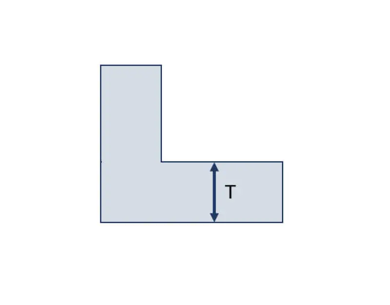
2. Radii
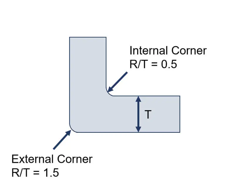
In injection molding, incorporating radii is crucial for avoiding sharp corners, which present challenges due to the properties of the molten material. Sharp, 90-degree corners impede the flow of the material, leading to areas of stress concentration that can compromise the integrity of the product. To mitigate this, the R/T ratio is applied in the design of mold corners, where “R” represents the radius and “T” denotes the adjacent wall thickness.
There are two types of corners to consider: internal and external. For typical applications, the internal corner is designed with an R/T ratio of 0.5, while the external corner adopts an R/T ratio of 1.5. This distinction ensures that both internal and external corners are optimized for material flow and structural integrity, as illustrated in Figures 1 and 2.
 |  |
|---|---|
| Figure.1 the mold before the radii | Figure.2 the mold after the radii |
3. Wall thickness
Wall thickness is a crucial factor in injection molding, as it significantly impacts the prevention of sink marks and warping in the final products.
Given the wide range of materials available for injection molding, selecting the optimal wall thickness can be complex. Therefore, we have identified the top 10 most commonly used materials in injection molding and provided recommendations for their respective wall thicknesses to ensure optimal product quality.
| Materials | Recommended Wall Thickness (inch) |
|---|---|
| Acrylic (PMMA) | 0.025 – 0.150 |
| Acrylonitrile Butadiene Styrene (ABS) | 0.045 – 0.140 |
| Nylon (PA) | 0.030 – 0.115 |
| Polycarbonate (PC) | 0.040 – 0.150 |
| Polyethylene (PE) | 0.030 – 0.200 |
| Polyoxymethylene (POM) | 0.030 – 0.125 |
| Polypropylene (PP) | 0.025 – 0.150 |
| Polystyrene (PS) | 0.035 – 0.150 |
| Thermoplastic elastomer (TPE) | 0.028 – 0.150 |
| Thermoplastic polyurethane (TPU) | 0.020 – 0.200 |
4. Undercuts
Undercuts are design features that hinder the removal of finished products from molds, as demonstrated in the animation below.
The left side of the animation depicts a product without an undercut, allowing for seamless ejection from the mold. Conversely, the right side illustrates a product with an undercut feature, which results in the finished product stuck in the mold.
 |  |
|---|---|
| Without undercut | With undercut |
5. Gates
The positioning and style of gates are vital for directing material into the mold cavity, as they dictate the force, angle, and temperature at which the material flows. These elements play a significant role in shaping the quality of the final molded product. To ensure optimal design and functionality of gates, follow these guidelines:
- Maintain a distance from cores and pins to prevent interference.
- Provide large space for easy gate removal.
- Reduce the length of the material flow path to enhance quality.
- Use multiple gates for complex or large parts to ensure even material distribution.
Adhering to these principles will lead to improved molding outcomes and higher quality parts.
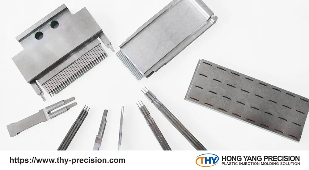
6. Ejector pins
Ejector pins are integral to the ejector system, tasked with removing the molded part from the mold cavity after the injection molding process concludes. They work in conjunction with other ejection mechanisms, like ejector blades and blocks, ensuring parts are efficiently and smoothly ejected post-molding. When selecting ejector pins, consider the following guidelines for optimal performance:
- Opt for Larger Diameter Pins: Larger diameter ejector pins are preferable as they ensure a more stable and smooth ejection process.
- Standardize Ejector Pin Sizes: Aim to use ejector pins of uniform sizes as much as possible. This simplifies the design process by reducing the need to accommodate multiple sizes.
- Minimize Distortion Risks: To prevent bending or distortion during ejection, it’s advisable to use ejector pins with a diameter exceeding 2.5mm. This ensures durability and reliability throughout the ejection phase.
3 Cosmetic Defects and How to Avoid Them
In the realm of injection molding, it’s crucial to go beyond the previously mentioned design rules and also address common defects that can arise in finished products. To mitigate these frequent issues, we offer design guidelines tailored to each type of defect, ensuring smoother injection molding processes.
1. Cracking
Cracks in finished products frequently form post-cooling, caused by residual internal stress which then results in surface damage. To mitigate this unexpected deterioration, several strategies can be employed:
Conventionally, there are three ways to address this issue:
- Increase the temperature of the mold to reduce internal stress.
- Increase the temperature of the material to decrease the injection pressure.
- Reduce the filling time and decrease the size of the mold’s gate.
However, certain specific factors can lead to failures:
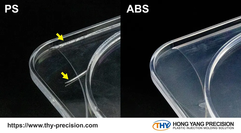
Using materials that are not appropriate for production can result in product cracking. For instance, employing PS might unexpectedly lead to cracks during the injection molding process. In this case, our seasoned engineers will advise clients to switch to alternative materials, like ABS, if the issue cannot be avoided.
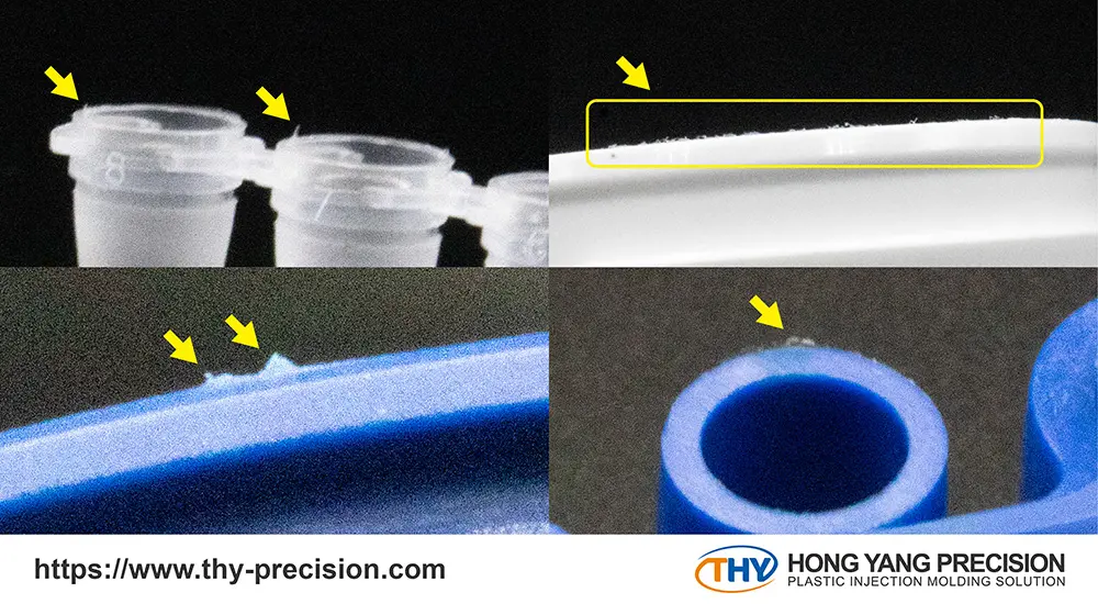
2. Finished raw edges
Raw edges are a frequent defect on the surfaces of injection-molded products, often resulting in an uneven finish. This issue is usually caused by poor mold design or inadequate injection molding conditions. These two solutions can effectively resolve the issue of unfinished raw edges:
- Ensure the injection molding conditions are appropriately set to prevent raw edge defects.
- Ensure tight clamping of male and female molds during injection to avoid misalignment or uneven surfaces, preventing full seal and resulting in burrs.
3. Record Groove
In injection molding, particularly at lower injection speeds, if the molten material cools too quickly upon contact with the mold surface, leading to excessive flow resistance, distortion can occur at the forefront of the flow.
This results in the solidified outer layer failing to fully adhere to the cavity walls, creating a wavy appearance (Record Groove). Once this wavy pattern solidifies, subsequent holding pressure is unable to correct it, leaving the imperfection permanent. Engineers can try to prevent this defects in advance:
- Accelerate the injection speed for the process.
- Raise the temperature of the molds and prevent temperature gradients within them.
Bringing Your Part Designs to Life with THY
Lacking expertise from professional designers and manufacturers can lead to increased costs and prolonged development times for products, often resulting in unexpected expenditures.
To circumvent these challenges and boost your product’s profitability, our experienced R&D engineers establish a complete design guideline for injection molding. Our goal is to craft your products with precision and reliability.
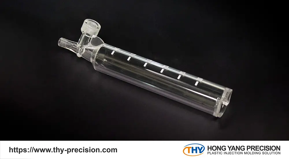
THY stands as a premier manufacturer of medical-grade and optical parts with tight tolerances (±0.001 mm), complemented by our high-grade cleanrooms (Class 8 and Class 7) for clients with specific needs to prevent unwanted contamination. Furthermore, we are proud to meet the ISO 9001 and the ISO 13485 standard.


Should you have any inquiries or face any design challenges, please do not hesitate to reach out to us.
Learn more about Injection Molding:
Injection Moulding: A Step-by-Step Process Breakdown
In-Depth Look at Injection Molding Machine Types & Uses